AI Roof Detection and Panel Placement: How AI Takes the Manual Work Out of Solar Design
Point at an address, get a finished design: that is the promise most solar software makes. The reality is two separate steps, not one. Here is what AI roof detection and AI panel placement actually do inside solarVis, and where each one hands the work back to you.
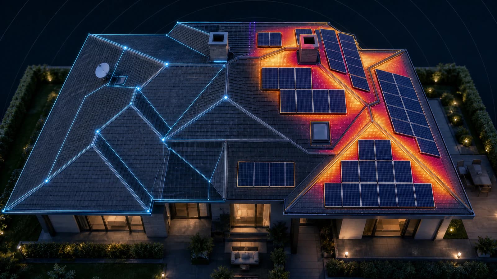
"AI roof detection" and "AI panel placement" get used as if they were one feature: point a tool at an address and a finished, buildable solar design appears. In practice they are two distinct steps with real capabilities and real limits, and understanding the difference matters if you are going to trust the output on a proposal. This blog explains what the two terms actually mean. Then it shows how each one works inside solarVis, the solar panel layout software behind 67,500+ solar projects. Coverage limits and manual-review steps included.
What "AI roof detection" actually means
At its core, AI roof detection is a computer vision problem: turning an aerial or satellite image into geometry a design tool can use. That means finding the roof outline, the internal lines where planes meet, and the boundaries of each distinct roof face.
Geometry alone is not a design, though. A roof outline with no slope or height assigned to it is a flat sketch, not a model you can run shading or production numbers on. The category of "AI roof detection" tools splits sharply between the ones that stop at 2D geometry and the ones that also infer a full 3D shape, usually by pulling in a second data source like LiDAR-derived elevation. Which side of that line a tool falls on determines how much work is left for a human afterward.
What "AI panel placement" actually means
AI panel placement is a different problem: given a roof's geometry and everything that constrains it, generate a layout of panels that meets a goal. That is not a grid fill. A real placement engine has to respect setbacks, work around obstacles and roof features, take shading into account so it is not wasting panels on a weak spot, and hit a sizing target rather than simply maximizing panel count.
Because of that, panel placement only means something once the inputs it depends on already exist: the roof geometry has to be real, and (as covered below) the shading has to already be calculated. A placement engine run before either of those is ready is optimizing against nothing.
How solarVis reads a roof
AI Roof Detection: a 2D wireframe, not a 3D model
Inside the Roof Drawing step, AI Roof Detection is triggered from the toolbar's sparkles icon. It analyzes satellite imagery for the project location and shows a "Detecting roof..." status while it works, then returns a 2D wireframe: the roof outline, the inner edges between faces, and the faces themselves.
That is the whole output. It does not assign slopes or heights to anything it finds, which means the result is not yet a 3D model. Two things also limit it in practice. First, availability is conditional: it only appears where high-resolution roof data covers the project's location, so it is not something every project can rely on. Second, it is a single undoable action, one undo restores the previous state, and the output is expected to need a human pass: missed edges and faces get fixed with the normal drawing tools before you move on.
Inner Edge Detector: geometry only, narrower scope
A related but separate tool, Inner Edge Detector, analyzes the angles of a roof outline you already have and generates a suggested inner line along the bisector of those angles. It is useful for filling in a hip or valley line quickly. Like AI Roof Detection, it is geometry only. It does not assign slopes either.
Going 3D: Fit to LiDAR or manual slopes
To turn a 2D wireframe into a real 3D model, there are two paths. Fit to LiDAR builds a true 3D model from LiDAR-based elevation data (available with the high-resolution, LiDAR-backed map layer). It sets the height of every point and the slope of every roof face automatically, replacing manual slope assignment entirely. It only needs the wall locations confirmed, and like AI Roof Detection, it is gated to zones with high data coverage.
Where Fit to LiDAR is not available, slopes are assigned manually: select a face or edge, set the slope in the right panel or drag the slope arrow, and that face becomes a 3D plane. Different faces on the same roof can carry different slopes, which matters for anything more complex than a simple gable.
Making the model physically real
A roof shape by itself still is not enough to place panels on with confidence. The Solar 3D Design and Simulation Roof Drawing step adds the features that determine what parts of a roof are actually usable:
- Obstacles (rectangles, circles, or polygons) mark chimneys, skylights, dishes, and anything else a panel cannot sit on. They block panel placement directly and factor into shading.
- Roof dormers come in three types, Shed, Gable, and Hip, each with adjustable width, length, and pitch.
- Parapet walls, from 0.1 to 3 meters high and 0.05 to 1 meter thick, cast real shadows and block panel placement the same way a physical wall would.
- Split Region separates roof sections sitting at different heights, which is how stepped roofs and additions are modeled correctly instead of as one flat plane.
Imagery itself comes from multiple map providers, including a high-resolution LiDAR-backed layer, or from custom imagery uploaded and aligned to the project. None of this is cosmetic: a layout is only as good as the model it is generated against, and a model missing a parapet wall or a dormer will place panels somewhere they cannot actually go.
AI Roof Detection and Fit to LiDAR both depend on data that is not uniformly available everywhere, and both produce output meant to be checked, not accepted blind. Building the obstacles, dormers, and parapets by hand is often exactly what happens after the AI step gets you most of the way there.
Why shading has to run before placement
Shading analysis, run from the sun button in the toolbar, is a hard prerequisite for AI Panel Placement. The placement engine does not work until it has been run, because placement decisions are made from its output.
The analysis produces color-coded irradiance heatmaps across the roof and, per panel, three inspector values: Solar Access, TOF (Tilt and Orientation Factor), and TSRF, the Total Solar Resource Fraction. Solar access captures how much sunlight is lost to shading; TOF captures the separate geometric penalty of a roof that does not face the optimal direction or angle. TSRF combines the two: TSRF = solar access × TOF. Our companion post on solar irradiance, shading, and string design covers how those numbers are calculated in more depth. What matters here is simpler: without them, there is no basis for ranking one roof face above another, which is exactly what placement has to do next.
How solarVis executes panel placement
Once shading has run, AI Panel Placement reads those results, ranks the roof faces, and fills all suitable faces at once, best spots first, while respecting setbacks, obstacles, dormers, and the shading results already described.
Two choices shape the output. First, a sizing target: panel count, annual production (kWh), DC power (kWp), or consumption offset percentage. Second, a mode:
- Max Production fills every placeable spot, prioritizing total energy harvest.
- Max Efficiency keeps only spots at or above 75 percent TSRF, resulting in fewer but better-performing panels.
That 75 percent figure is worth pausing on, because it is the most telling detail of how this feature was designed. It is not an arbitrary slider default. Several solar incentive and quality programs treat a TSRF at or above 75 percent as the benchmark for a well-sited array, and some rebates set an explicit minimum in that range. Max Efficiency mode encodes that exact siting convention directly into the layout engine, rather than inventing its own quality bar.
A prune slider builds on the same idea, but it works on the finished layout rather than on the rules that produced it. Once AI Panel Placement has filled the roof, raising the slider's TSRF threshold highlights the already-placed panels that fall below it in red, and applying commits that trim. You are editing a layout that exists, not setting a constraint the engine designs against. Beyond the automated modes, Fill Roof Face places panels on one selected surface at a time, and manual drag-to-place, grouping, and duplication remain available for hand-tuning any part of the result. That finished layout is also what everything downstream reads: panel count, production, and the roof view itself carry straight into the solar proposal software that turns the design into a customer-facing document.
What to look for in PV design software
Most tools in this category now advertise automation. The differences that matter are in what the automation actually produces, so these are the questions worth asking of any PV design software before you commit a design team to it.
Does roof detection stop at 2D, or produce a real 3D model? A 2D wireframe still needs slope and height assigned before you can simulate anything. A tool that pulls elevation data and lifts the roof automatically removes a step that a wireframe-only tool leaves on your desk.
Is availability checked per address, and what happens when coverage is missing? Detection quality depends on the underlying data, and no provider covers everywhere. What matters is whether the fallback drawing tools are good enough that the workflow still works on every project, not just the well-mapped ones.
Is the layout engine shading-aware, or only geometric? A solar layout tool that fills a roof by shape alone will happily place panels somewhere that never earns its keep. Ranking faces by measured solar access is what separates real solar design automation from a grid fill.
Can you steer it to a target and a quality threshold? Being able to size to a production figure or a consumption share, and to set a floor like 75 percent TSRF, is the difference between a layout you can defend to a customer and one you have to justify after the fact.
Is the output editable? Any generated layout will meet an edge case it did not anticipate. The engine should give you a fast, consistent starting point that you can then override panel by panel.

